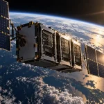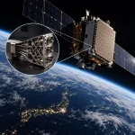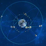

A satellite may have flown far beyond visual range, yet subsystem engineers can still see on their screens that a particular unit is at 23.6°C, drawing 1.8 A from the bus and operating on its primary channel. They may even be able to determine that a heater has just switched on. It may look as though someone has connected a multimeter to equipment hundreds of kilometers away, but the information has actually traveled through a long space-to-ground data chain.
The satellite does not directly transmit the characters “23.6°C” to the ground. A sensor first converts temperature, voltage, current or switch position into an electrical signal, which an acquisition circuit digitizes. The spacecraft then organizes the data in an agreed format, adds information such as packet identifiers, sequence numbers and timestamps as required by the mission design, and passes it to the TT&C equipment for downlink. Ground systems interpret the corresponding fields as degrees Celsius, volts, amperes or switch states according to the specified data format and parameter definitions. When action is required, the ground sends a telecommand through a separate link and uses subsequent telemetry to confirm the result.
Three terms must first be distinguished: telemetry brings satellite status data down to the ground; telecommand sends ground instructions up to the satellite; and tracking and orbit determination establish where the satellite is and how it is moving. Together, these functions constitute what is commonly known as the telemetry, tracking and command, or TT&C, link.
What the ground sends is a telecommand, while what the satellite transmits is telemetry. Even if a command requests a particular telemetry set, changes the telemetry format or controls data playback, it remains a telecommand in terms of its space-to-ground communications function. Orbital position may also be obtained through separate ranging, range-rate, angular tracking and orbit-determination processes. ESA’s public definition of TT&C likewise distinguishes these three functions.[1][12]
1. What Exactly Do Engineers See on Their Screens?
Subsystem engineers usually examine the engineering telemetry of the spacecraft platform or payload, also known as health-and-status data or housekeeping data. Typical examples listed by NASA include temperature, pressure, voltage, computer status and equipment switch states. These parameters support satellite health assessment and operations and are distinct from mission data such as camera imagery, radar echoes or scientific measurements.[2]
A thermal-control engineer, for example, may simultaneously examine battery temperature, propulsion-line temperature, heater switching status and total spacecraft power consumption. A power engineer is more concerned with bus voltage, battery charge and discharge currents, solar-array output and the status of individual power-distribution channels. An attitude and orbit control engineer may examine attitude quaternions, angular velocity, sensor-validity flags and actuator status. Each discipline sees a different projection of the same satellite through its respective interfaces.
The displayed value of 23.6°C is the final output of an entire measurement chain. What is physically installed on the equipment is normally only a temperature-sensing element. The acquisition circuit reads its electrical signal and produces a digital value, which the ground then converts into temperature using a calibration relationship. Some spacecraft perform this conversion onboard before transmission, but the underlying principle remains the same: every displayed value must be traceable to a specific measurement point, sampling time and conversion relationship. If the satellite is outside the coverage of a ground station, the screen may show data from the previous contact pass or data recorded onboard and played back during the next pass.
A single unit may contain dozens—or even more—internal points worth monitoring. However, limitations involving the number of sensors, interface resources, onboard bandwidth and power consumption mean that only some of them are ultimately included in the telemetry definition. The ground cannot see data that have no sensor, no acquisition channel or no place in the downlink. Decisions about which parameters require continuous monitoring, which need to be read only in diagnostic mode and which failures must be inferred from multiple external indications should be made during the system-design phase.
Telemetry is the digital observation of physical states. To understand a parameter, engineers must know at least where it is measured, when it was sampled, how it was converted and whether the current display represents a real-time stream or historical playback.
2. How Temperature, Voltage and Switch States Become Telemetry
This process can be understood in four steps. First, engineers select a location that needs to be observed—the measurement point. Next, the physical change is converted into an electrical signal. An acquisition circuit then digitizes the electrical signal. Finally, the digital value is interpreted as degrees Celsius, volts, amperes or a switch state according to the parameter definition. In essence, telemetry allows the ground to read measurement points that were deliberately incorporated into the spacecraft.
Temperature: From a Warming Equipment Enclosure to a Displayed Value of 23.6°C
Suppose engineers need to monitor the enclosure temperature of a particular unit. The first step is to install a thermistor or resistance temperature detector at a specified location on the enclosure. Both are temperature sensors: their resistance changes as the temperature changes. The sensor cannot report “the current temperature is 23.6°C”; it can only represent temperature changes through changes in electrical resistance.
The second step is to make that change readable by the acquisition circuitry. Engineers connect the sensor to a signal-conditioning circuit. “Conditioning” means converting a resistance change that cannot conveniently be read directly into a stable voltage signal of an appropriate magnitude, while providing amplification, filtering and protection where necessary. At this point, the circuit has produced a voltage—not a temperature.
The third step is to convert the voltage into a number that a computer can process. This is performed by an analog-to-digital converter, or ADC. An ADC functions like a digital ruler: it divides a continuously varying voltage into discrete levels and produces an integer for each sample. A 12-bit ADC, for example, normally produces integers from 0 to 4,095. This quantized digital code is referred to here as a raw value; it is not yet a temperature in degrees Celsius.
In the fourth step, onboard or ground software performs the conversion using a calibration relationship. “Calibration” means testing the complete measurement chain against known temperatures in advance and establishing a table or curve that maps raw values to degrees Celsius. Only after this process can a raw value be displayed as 23.6°C. Showing one decimal place is merely a display format; it does not mean that the complete measurement chain is accurate to 0.1°C. Replacing the sensor, wiring or acquisition channel may change the conversion relationship, so raw values cannot be interpreted independently of their parameter definitions.
The complete temperature-telemetry process is: enclosure temperature changes → sensor resistance changes → the conditioning circuit converts the change into voltage → the ADC produces an integer raw value → the calibration relationship converts it into degrees Celsius.
The displayed temperature must also be interpreted together with the measurement location. A sensor attached to an equipment enclosure only indicates the temperature near that point. It does not necessarily represent the temperature of an internal chip or the equipment mounting interface. Subsystem engineers must first determine exactly where the temperature is measured and then assess it in conjunction with equipment power consumption, the thermal design and ground-test results.
Voltage and Current: Scale or Convert First, Then Reconstruct the Engineering Value
Voltage telemetry follows the same principle as temperature telemetry, although the front-end components are different. If the bus voltage exceeds the range that the acquisition electronics can tolerate, it must first be reduced—through a voltage divider, for example—to an acceptable level. Filtering and protection are added as required, and electrical isolation may be used when necessary. The ADC reads the adjusted voltage, after which the onboard or ground system reconstructs the original value according to the conversion relationship. Only then does the bus voltage appear on the screen.
Current is also normally measured indirectly. One common method uses a current-sensing element in the current path to convert the current into a small voltage. A Hall-effect sensor may alternatively convert the current into an acquirable signal while maintaining electrical isolation. The remainder of the process is unchanged: the ADC produces a raw value, which is converted into amperes using calibration coefficients.
The displayed reading “branch current: 1.8 A” is therefore not transmitted directly as those characters. It is reconstructed through the sequence “actual current → measurement signal → ADC raw value → 1.8 A.” If the measurement range is too wide, small changes in current may be difficult to distinguish. If it is too narrow, an abnormal current may exceed the range and cause the displayed value to remain at its upper limit—a condition known as acquisition saturation.
Switches and Relays: A 0 or 1 Represents a Defined State
Temperature and current vary continuously, whereas on/off conditions normally have only two states and are therefore known as discrete signals. Interface circuitry identifies the two electrical states as 0 and 1, after which the spacecraft data-handling system assigns a parameter name to that bit. It may be called “heater command status” or “relay contact status.” Although the names sound similar, the signals may be measured at different points.
Consider the activation of a heater. Engineers can check the operation at five levels: a change in the command state to 1 indicates that software has requested activation; a drive readback indicates whether the power driver is producing an output; an auxiliary contact indicates whether the relay contact has reached the commanded position; an increase in branch current shows that the heater is receiving power; and a subsequent rise in nearby temperature confirms that the heating action has produced the intended effect.
Exactly what a drive readback proves depends on where it is obtained. A signal taken from an actual driver-output monitoring point can indicate that the driver circuit is producing an output. If it is merely a readback of a command register, it mainly confirms the software setting. An auxiliary contact is a separate contact set on a relay that indicates its mechanical position. A particular satellite may not downlink all five types of information, but engineers must know whether the 0 or 1 they are examining comes from software, the drive circuit or a physical contact.
Valves, motors and hold-down and release mechanisms follow the same logic. Commanding an action, supplying drive power, reaching the required mechanical position and producing the intended effect are separate levels of evidence. When examining a status bit, engineers should first consult the parameter definition and signal source, and then seek independent confirmation from current, position, temperature, pressure or other parameters.
3. How Does a Spacecraft Organize Thousands of Parameters?
Equipment commonly provides status information to the spacecraft data-handling system in one of two ways. Analog and discrete signals from temperature sensors, voltage-monitoring circuits and auxiliary contacts can be read centrally by onboard acquisition boards or remote acquisition units. Digitally controlled equipment containing its own processor can also report status words, fault codes and internal measurements directly through a bus or serial interface. These data ultimately enter the onboard computer or data-management equipment. Device names vary between spacecraft, but every data source should be traceable to a particular measurement point, interface or software variable.
During the design phase, equipment engineers must agree with system, data-handling and TT&C engineers on the name and source of each parameter, its normal range, sampling interval, raw-data conversion method, the meanings of 0 and 1, and the flags used for abnormal or invalid data. The spacecraft data-handling system cannot automatically understand the physical meaning of a particular 2.3 V signal or a bit set to 1. Those meanings must be fixed consistently in interface documents, telemetry parameter tables and the ground database.
Rapidly changing attitude angular rates may require relatively high sampling frequencies, while slowly changing structural temperatures can be sampled much less frequently. Critical fault parameters may be transmitted periodically, with the sampling rate increased or an event record inserted when a limit is exceeded. Sampling too slowly can miss transients, while sampling too quickly consumes onboard processing, storage and downlink resources. Much of telemetry design consists of balancing observability against available resources.
In missions using the CCSDS framework, application data may first be assembled into space packets containing application identifiers, sequence information and mission-defined data fields. Multiple packets are then inserted into telemetry transfer frames. Timestamps, quality flags and parameter organization are defined by the individual mission; no single project format should be treated as universal across all satellites. The CCSDS Space Packet Protocol and TM Space Data Link Protocol provide a layered transport framework.[3][4]
Once loaded into telemetry frames, the data still consist only of a sequence of 0s and 1s and cannot yet cross space. They must pass through the telemetry transmission chain, undergoing channel coding, modulation, frequency conversion and power amplification before becoming radio signals that can be radiated by an antenna. Different missions may employ different combinations of modulation and coding, with telemetry synchronization and channel-coding methods selected from the relevant CCSDS standards where applicable.[5]
4. How Is Telemetry Downlinked From the Satellite?
To “downlink” telemetry means placing the satellite’s digital data onto radio waves and transmitting them through the spacecraft antenna to the ground. Radio equipment first generates a stable high-frequency signal known as a carrier. The modulator then changes the carrier’s phase, frequency or other characteristics in a controlled manner according to the 0s and 1s in the data. In this way, digital information that originally existed only inside a computer is encoded onto electromagnetic waves capable of propagating through space.
Synchronization information and channel coding are normally added before modulation. Synchronization information helps the receiver determine where a frame begins, while channel coding introduces redundancy so that some transmission errors can be detected or corrected. After modulation, the signal is converted to the designated TT&C frequency band and amplified by a power amplifier before being sent to the spacecraft’s TT&C antenna. The antenna converts the high-frequency electrical signal in the circuit into electromagnetic waves radiated into space. Only at this point does the telemetry physically leave the satellite.
As the electromagnetic waves travel away from the satellite, their energy spreads over an ever-larger area, leaving only a very small fraction available at the ground. A ground station uses the predicted orbit to calculate the time, azimuth and elevation of each pass, enabling its high-gain antenna to acquire the signal when the satellite rises above the horizon and to track the Doppler shift caused by its motion. A pass by a polar-orbiting satellite may last only several minutes to slightly more than ten minutes. The mission center must schedule the station network, frequency, data rate and reception plan in advance. ESA’s MetOp operational information, for example, describes contact windows lasting four to 12 minutes.[9]
Ground reception is broadly the reverse of onboard transmission. The ground antenna first converts the weak electromagnetic waves into a high-frequency electrical signal. A low-noise amplifier strengthens it while introducing as little additional noise as possible. Downconversion equipment then shifts the high-frequency signal into a band that is easier for the receiver to process. The receiver subsequently performs carrier and symbol synchronization, demodulation, synchronization-marker detection and channel decoding according to the communications scheme in use. This restores the transfer frames for data-link processing, from which space packets and parameter data can be extracted. The exact order of synchronization and decoding depends on the coding method and frame structure.
The recovered data are then delivered to mission-control, flight-dynamics or payload-processing systems. Ground software identifies the packet or frame type, extracts data from the relevant field positions and uses the units, ranges, state definitions and calibration relationships stored in the telemetry database to convert raw values into engineering values such as 23.6°C, 1.8 A or “on.” At this point, the complete “measurement–downlink–ground display” process has been completed for a particular status parameter. Public information from ESA and NASA likewise identifies telemetry processing, archiving, display and telecommand generation as basic capabilities of ground mission systems.[8][10]
Engineering interfaces must also distinguish real-time telemetry from delayed playback. Playback data were recorded onboard while the satellite was outside ground-station coverage and are downloaded later during a pass. They may arrive interspersed with the real-time stream. When examining a plot, engineers must distinguish the sampling time, packet-generation time and ground-reception time and confirm exactly what each timestamp represents. Parameters displayed on the same screen or contained in the same packet may still have different sampling and update cycles and should not automatically be assumed to describe the same instant.
Ground interfaces use the database to plot curves, compare values against limits, indicate data validity and preserve historical records. For anomaly investigation, when a parameter was sampled onboard is generally more important than when it reached the ground. If data become stale or stop updating, the interface should provide a clear indication to prevent the last valid value from being mistaken for the current state. Radio-link design must jointly consider transmitter power, antenna gain, propagation loss, data rate, modulation and coding, receiver performance and link margin.
5. Is the Satellite Position Shown on the Screen Measured Directly Through Telemetry?
Some satellites carry GNSS receivers that calculate position and velocity onboard and downlink the navigation solution as telemetry parameters. In such cases, onboard navigation equipment is indeed one source of the state vector shown on the ground. It is not, however, the only source of orbital information.
Ground TT&C stations can also perform radio ranging and range-rate measurements. Round-trip signal-propagation time provides range information, while Doppler or phase changes provide line-of-sight velocity. Some systems also use angular measurements. The flight-dynamics system combines these observations with dynamic models incorporating Earth’s gravity, atmospheric drag, solar and lunar gravity, maneuver information and other factors. It then estimates the satellite’s position, velocity and associated uncertainty at a particular time and propagates the orbit forward to produce ephemerides. NASA and ESA list tracking separately from telemetry and command precisely because orbit determination is not synonymous with ordinary temperature telemetry.[1][11]
The longitude, latitude, altitude, semi-major axis, eccentricity and inclination displayed by a ground system may therefore come from onboard GNSS, a ground-generated orbit solution or a fusion of the two. Engineers using these values must check the time reference, coordinate system, data source and orbit-solution version instead of focusing only on a displayed “current position.”
6. How Does the Ground Send Telecommands Back to the Satellite?
Telecommand operations usually begin with a mission requirement. A subsystem team specifies the intended operation and its prerequisites. The mission-control team converts these into an individual command or command sequence and checks the spacecraft mode, available electrical power, attitude, TT&C window and potential conflicts. Important operations are often rehearsed using simulation software or a ground engineering model. NASA’s information on small-spacecraft ground systems states that mission teams generate command plans, simulate spacecraft responses and, when confidence is insufficient, verify commands on an engineering model before approving their upload.[8]
When an operator selects “heater on” or “unit power on” through the ground interface, the system first generates a digital instruction that the satellite can recognize. This normally includes the target equipment, action or parameter, sequence information and transmission-error checks. Once approved, the digital data are placed in a telecommand transfer frame and then encoded onto a carrier through synchronization, channel coding and modulation. A power amplifier strengthens the signal, and the ground-station antenna converts it into electromagnetic waves directed toward the satellite. This is the physical process of telecommand uplink. The CCSDS TC Space Data Link Protocol and synchronization and channel-coding standards define the general link mechanisms.[6][7]
After the spacecraft’s TT&C antenna receives the uplink, it converts the electromagnetic waves into a very weak high-frequency electrical signal and passes it to the onboard receiver. According to the communications scheme in use, the receiver performs radio-frequency reception, downconversion, synchronization, demodulation and channel decoding to recover the telecommand transfer frame. The exact processing relationship again depends on the coding method and frame structure. The system then checks whether the transmission data contain errors, whether the destination address belongs to the spacecraft, and whether the command format and parameters meet the specified requirements. Only after these checks does it pass the command to onboard software or dedicated command-decoding equipment.
A transmission-error check mainly determines whether data were corrupted in transit, while the spacecraft-address check determines whether the data were intended for that spacecraft. Neither alone proves that a command came from an authorized source. Depending on the mission’s security requirements, authentication, integrity protection and anti-replay mechanisms may also be implemented to prevent unauthorized commands or the re-execution of old commands.[13]
The final stage is onboard routing. Commands for digital equipment may be sent through an onboard bus or serial interface. Commands for relays, heaters, valves or similar devices may first be routed by the onboard computer to power-distribution or drive equipment, where a drive circuit generates the actual switching signal. Simple commands can be executed immediately. Time-tagged commands are stored and triggered at the specified time. Parameter-loading commands modify thresholds, mission tables or control parameters, while procedural commanding arranges multiple actions in sequence.
Not every command directly actuates a relay. Many commands first change a software mode or mission parameter, after which onboard control logic drives the hardware when the required conditions are met. The more autonomous a satellite becomes, the more likely the ground is to provide objectives, plans and constraints instead of specifying every individual action.
After the satellite receives, distributes and executes a command, it places the relevant status information into the telemetry stream and returns it through the downlink. The available confirmation levels and level of detail vary between missions. Some distinguish command acceptance, execution start, execution progress and execution completion. A ground display showing “sent” does not mean that the satellite has received the command. A spacecraft report showing “accepted” does not mean that the hardware action has been completed. Engineers must also determine the criteria on which an “execution successful” report is based.[12]
For a heater activation, a command-verification report may indicate how far the onboard processing has progressed, while branch current and nearby temperature confirm the actual physical effect. The directions must still be kept clear: the telecommand travels from the ground to the satellite, while the acceptance status, execution status and resulting parameters sent back by the satellite are all telemetry.
7. How Thoroughly Must the Two Space-to-Ground Links Be Tested Before Launch?
The measurement chain must first be calibrated. For analog parameters such as temperature, voltage and current, known values are applied across the specified environment and measurement range to verify the total error after sensing, conditioning, acquisition and ground conversion. For discrete parameters, every 0 and 1 must be checked against the corresponding physical state. Parameter identifiers, units, signs and decimal-place formatting must also be verified.
Equipment-interface, integrated spacecraft data-chain and radio-frequency link tests then follow. Beginning with sensors or equivalent signal sources, engineers verify that the data can pass through the spacecraft data-handling system, TT&C transmitter, radio link and ground software and be recovered correctly. They then generate telecommands on the ground and verify onboard reception, routing, execution and result readback. Space-to-ground integration testing is valuable because it brings independently validated onboard equipment and ground systems together to verify their interfaces.
Telecommand testing should also cover incorrect addresses, illegal parameters, duplicate or expired commands, incompatible spacecraft modes, execution interlocks and communications interruptions. High-risk operations require verification of authorization, prerequisites, abort capability and anomaly-recovery paths. The ground display must be tested for out-of-limit alarms, invalid values, distinctions between real-time data and historical playback, and clear warnings when data become stale or stop updating.
Once the satellite is in orbit, subsystem engineers do not directly “see” the equipment operating far above Earth. What they see is a state model that has been deliberately designed, calibrated and transmitted. Likewise, a command is not a physical control wire stretching across space, but a set of telecommand data that has been reviewed, encoded and verified.
A reliable in-orbit operational loop can be summarized in four steps: measure the state accurately, return the data to the ground, make the correct assessment and use new telemetry to confirm the effect of the command. Only when telemetry values can be traced to actual measurement points and telecommand results can be verified through the relevant status parameters does a dependable operational closed loop truly exist between space and ground.
A reliable space-to-ground operational loop begins well before launch, with robust system design, interface coordination, integration and end-to-end testing. As China brings more satellite manufacturing capacity to the global market, STARPATH GLOBAL connects international customers with competitively priced satellite, payload and AIT solutions. Mission teams can contact STARPATH GLOBAL to discuss requirements and identify a practical path from integration and testing to final delivery.
References
[1] European Space Agency, TT&C and PDT Systems and Techniques section, public definitions of telemetry, tracking and command.
[2] NASA Science, Basics of Space Flight, Chapter 8: Experiments; Chapter 11: Onboard Systems, descriptions of engineering telemetry and onboard data processing.
[3] CCSDS 133.0-B-2, Space Packet Protocol, Issue 2, June 2020.
[4] CCSDS 132.0-B-3, TM Space Data Link Protocol, Issue 3, October 2021.
[5] CCSDS 131.0-B-6, TM Synchronization and Channel Coding, Issue 6, April 2026.
[6] CCSDS 232.0-B-4, TC Space Data Link Protocol, Issue 4, October 2021, including the October 2023 technical corrigendum.
[7] CCSDS 231.0-B-4, TC Synchronization and Channel Coding, Issue 4, July 2021, including the July 2026 technical corrigendum.
[8] NASA Small Spacecraft Systems Virtual Institute, State-of-the-Art of Small Spacecraft Technology: Ground Data Systems and Mission Operations, page updated May 11, 2026.
[9] European Space Agency, MetOp: Operations, descriptions of contact windows lasting four to 12 minutes and pass operations.
[10] European Space Agency, MetOp-SG Operations and Data Flow; Sentinel-2 Operations; Envisat Operations, descriptions of platform telemetry, telecommand, tracking and ground mission control.
[11] NASA Science, Basics of Space Flight, Chapter 18: Deep Space Network, descriptions of tracking, telemetry, command and orbit determination.
[12] ECSS-E-ST-70-41C, Space Engineering: Telemetry and Telecommand Packet Utilization, April 15, 2016.
[13] CCSDS 355.0-B-2, Space Data Link Security Protocol, Issue 2, July 2022.