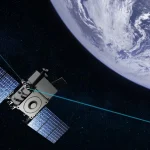

A satellite entering low Earth orbit (LEO) may lead people to assume that there is almost no atmosphere outside, so how could oxygen still exist?
However, for spacecraft operating in LEO, oxygen is not only present but can become one of the most challenging environmental factors for materials. It can gradually thin polyimide films, create fiber-like microscopic textures on organic coating surfaces, oxidize and peel away silver interconnects, and even penetrate through pinholes in protective coatings to slowly erode the underlying polymer substrate.
This oxygen is not the molecular oxygen (O₂) that humans breathe, but Atomic Oxygen. In engineering documents, it is commonly abbreviated as AO or ATOX. It is a recognized factor in spacecraft space-environment durability design. China’s current recommended national standard GB/T 40519-2021 is titled Design Requirements for Atomic Oxygen Protection of Spacecraft.[1]
Atomic oxygen risk cannot be assessed simply by saying “this material is atomic-oxygen resistant.” Engineering analysis must first calculate the cumulative atomic oxygen fluence based on orbit and attitude, then use test data from specific materials, coatings, and structural configurations to predict degradation, while also accounting for pinholes, folds, edges, and manufacturing variations in lifetime verification.
1. If Space Is Nearly Empty, Where Does Atomic Oxygen Come From?
Near Earth’s surface, oxygen mainly exists as O₂ molecules. At several hundred kilometers altitude, short-wavelength solar ultraviolet radiation breaks some oxygen molecules apart into individual oxygen atoms. Because the atmosphere is extremely thin at these altitudes, collisions between oxygen atoms and opportunities to recombine into O₂ are greatly reduced, allowing atomic oxygen to persist.
Three concepts must be distinguished here. Atomic oxygen is a neutral single oxygen atom, not an oxygen ion. Its primary impact is surface chemical reaction and material erosion, rather than total ionizing dose (TID) or single-event effects (SEE) in electronic components. It is also different from ozone (O₃), which is commonly discussed in terrestrial laboratories.
Although the surrounding gas is extremely sparse, a spacecraft in LEO travels at an orbital velocity of approximately 7.5–8 km/s. From the perspective of the spacecraft surface, it is as if the vehicle is continuously colliding head-on with oxygen atoms. If the kinetic energy is estimated only from oxygen atom mass and a velocity of 7.8 km/s, the result is approximately 5 eV. In reality, spacecraft-relative atmospheric velocity, atmospheric co-rotation, and atomic thermal motion must also be considered. Therefore, a more accurate description is that LEO ram-facing atomic oxygen impacts occur at an energy level of several electron volts, with NASA commonly using about 4.5 eV to characterize the typical LEO environment.[2]
This energy is far lower than that of high-energy protons or heavy ions, but it is sufficient to drive many surface chemical reactions. For carbon-based polymers that produce volatile oxidation products, each collision removes only a tiny amount of material. However, after exposure to enormous cumulative atomic oxygen fluence, these microscopic losses become measurable reductions in thickness, mass, and material performance.

Figure 1: Solar short-wavelength ultraviolet radiation dissociates oxygen molecules, while LEO spacecraft experience high-speed collisions with neutral atomic oxygen. Source: Author’s illustration based on publicly available NASA and ESA information.
2. Which Orbits Require the Most Protection? Altitude Is Only the First Input
Atomic oxygen is primarily a LEO concern. The ECSS space environment standard identifies neutral atmospheric density, composition, and aerodynamic effects below approximately 1000 km as requiring analysis, and notes that high atomic oxygen fluxes can cause surface corrosion of spacecraft and sensitive instrument coatings.[3]
Altitude Determines the Overall Trend, While Perigee Often Dominates Exposure in Eccentric Orbits
Generally, the lower the orbit, the denser the residual atmosphere and the higher the direct atomic oxygen flux. ESA’s GOCE gravity-field satellite operated at an extremely low altitude of about 250 km. To achieve improved gravity measurements, it had to fly at this altitude, and its ram-facing external coatings were specifically designed to withstand high atomic oxygen flux.[4]
Circular orbits can be approximately analyzed using a single altitude. Eccentric orbits cannot be evaluated simply by averaging perigee and apogee. During each perigee pass, spacecraft velocity increases while atmospheric density may also rise significantly. Short periods of intense exposure can contribute substantially to total accumulated fluence. Whether perigee dominates must be determined by integrating density and velocity along the orbit rather than relying only on average orbital altitude.
Inclination Does Not Directly Create Atomic Oxygen, but Determines Which Regions a Satellite Samples
Orbital inclination determines the range of latitudes a spacecraft can access. Right ascension of the ascending node (RAAN) and orbital precession determine the orientation of the orbital plane relative to the Sun and the local solar time of passes. Since upper-atmosphere temperature and composition vary with latitude, day-night conditions, and season, satellites with different inclinations and orbital planes may experience different atomic oxygen density histories.
However, it is incorrect to state that “higher inclination means more atomic oxygen.” Inclination changes the sampling path through the environment; it is not a direct amplification factor.
Sun-synchronous orbits maintain relatively stable local crossing times, which benefits consistent illumination conditions for remote sensing, but they do not mean the atomic oxygen environment is constant. Solar activity, geomagnetic disturbances, seasons, and orbital altitude still vary. Atmospheric co-rotation and upper-atmospheric winds also modify spacecraft-relative velocity. Prograde, retrograde, and different inclination orbits can experience differences, although atmospheric density variation is usually the more sensitive factor for most LEO missions.
Solar Activity Can Change the Same Orbit’s Environment
When solar extreme ultraviolet radiation increases, the thermosphere heats and expands upward. Geomagnetic activity also changes upper-atmosphere temperature and density. Therefore, even a 500 km circular orbit can experience different atomic oxygen conditions in different years and under different space-weather conditions.
Engineering models commonly use F10.7 solar flux to characterize solar activity and Ap indices to describe geomagnetic activity. Designers typically analyze nominal, elevated, and bounding environments over the mission duration rather than calculating only the conditions on launch day.
Orbital Decay Makes the Environment Time-Dependent
LEO satellites experience atmospheric drag from the residual atmosphere, which can gradually reduce altitude. Lower altitude increases atmospheric drag and atomic oxygen density, creating a feedback effect.
Atomic oxygen lifetime analysis therefore cannot always use the initial orbit alone. If a mission involves natural decay, active lowering maneuvers, or frequent orbital adjustments, predicted orbital evolution should be included in the environmental model to cover potentially harsher late-mission conditions.
Orbit Determines “Which Environment,” Attitude Determines “Which Surface Gets Hit”
Surfaces facing the velocity vector generally receive the highest directional flux. Wake-side surfaces, shadowed regions, and recessed structures experience lower exposure due to reduced direct flux, but they are not completely immune because thermal-motion and scattered atomic oxygen can still reach them.
Solar array rotation, antenna deployment, yaw maneuvers, safe modes, and orbit adjustments can redistribute cumulative exposure across spacecraft surfaces. NASA’s analysis of the Long Duration Exposure Facility (LDEF), for example, incorporated altitude, latitude, longitude, local solar time, spacecraft velocity, orbital precession, and solar activity rather than replacing the complete environment with a single “orbital altitude” value.[13]
Therefore, whether a satellite requires significant atomic oxygen protection depends on multiple factors, including altitude and eccentricity, inclination and orbital plane, local time, mission duration, orbital decay, solar and geomagnetic activity, attitude history, surface orientation, and structural shielding.
GEO, lunar, and typical deep-space missions generally do not treat Earth atomic oxygen as a dominant environmental factor, but they still require analysis of their specific neutral atmosphere and plasma environments. “Not LEO” does not mean “no surface chemical risks.”
3. Engineering Calculation: From Atomic Oxygen Density to Material Loss
The first step in atomic oxygen protection is not selecting a coating, but defining the mission environment. A common approach is to use neutral atmospheric models such as NRLMSISE-00 along the spacecraft trajectory to calculate atomic oxygen density at different times and locations. Model inputs include not only altitude but also latitude, longitude, time, solar flux F10.7, and geomagnetic activity Ap.[3][5]
Step 1: Direct Surface Flux
Fdir ≈ nO vrel cosθ
where nO is atomic oxygen density, vrel is spacecraft-relative atmospheric velocity, and θ is the angle between the incoming direction and the surface normal.
This simplified equation applies only to directly exposed surfaces with 0°≤θ≤90°. More complete analyses include atmospheric co-rotation, winds, attitude changes, structural shielding, atomic oxygen thermal motion, and surface scattering.
Atomic oxygen density is usually expressed in atoms/cm³, while relative velocity is expressed in cm/s. Their product gives atoms/(cm²·s), the unit of atomic oxygen flux.
Step 2: Cumulative Atomic Oxygen Fluence
Φ(x) = ∫ F(x,t) dt
where x represents a specific spacecraft surface location.
Flux describes how many atoms arrive per square centimeter per second; fluence describes the total number accumulated over the mission, usually expressed as atoms/cm².
Fluence is the key input for material lifetime calculations.
Step 3: Estimating Thickness Loss of Uniform Bare Materials
Δh ≈ Ey × Φ
Ey is the atomic oxygen erosion yield, representing the volume of material lost per incident oxygen atom, commonly expressed in cm³/atom. When cm³/atom is multiplied by atoms/cm², the result is cm, which directly corresponds to the thickness loss.
If mass loss needs to be calculated, assuming uniform exposure and known area A and density ρ, it can be expressed as Δm≈ρAΔh≈ρA EyΦ. NASA-HDBK-6024 gives a typical low Earth orbit erosion yield for Kapton H of 3.0×10⁻²⁴ cm³/atom. Assuming a bare Kapton H film accumulates a fluence of 1.0×10²¹ atoms/cm², the simplified calculation gives Δh≈3.0×10⁻³ cm, or approximately 30 μm.[2] This value is only intended to illustrate unit conversion and order of magnitude, and does not represent the lifetime prediction of any specific spacecraft.
The above equation relies on three important assumptions: the material is uniformly exposed, erosion is approximately uniform, and Ey can be treated as a constant within the analyzed fluence range. For some polymers containing inorganic fillers, materials that form residual surface layers, or polymers whose surface state evolves continuously, the erosion yield may change with fluence. In such cases, the more rigorous expression is Δh=∫Ey(Φ)dΦ. Design analyses must use data matched to the specific material grade, manufacturing process condition, and target fluence.[2]
The relationship Δh≈EyΦ is suitable for estimating surface recession of uniformly exposed bare materials or uniform sacrificial layers. For polymers protected by inorganic coatings, service life is often governed by pinhole density, crack propagation, edge exposure, and undercutting beneath the coating. Therefore, the approach of simply dividing “coating thickness by the bare-material recession rate” cannot be used as a prediction of protection lifetime.

Figure 2: Environmental models provide atomic oxygen density; velocity, attitude, and surface orientation determine flux; mission integration produces fluence, which is linked to material response data. Source: Author’s illustration.
4. How Does Atomic Oxygen “Eat” Spacecraft Materials?
For many carbon-based polymers, atomic oxygen first removes hydrogen or attacks carbon bonds at the surface, creating oxygen-containing functional groups. Continued reactions can produce volatile products such as CO and CO₂ that leave the surface. Macroscopically, materials lose mass and retreat in thickness; microscopically, directional atomic oxygen exposure creates cone-like, fibrous, or grooved surface structures.[6]
Thermal blankets and polyimide films are among the most visible examples. Bare polyimide can become thinner and rougher, reducing mechanical strength and elongation. Surface solar absorptance, infrared emissivity, and scattering characteristics may also change.
Solar arrays and flexible circuits are not simply destroyed at the solar cell level. Risks are concentrated in organic substrates, cover-film edges, adhesives, insulation layers, and exposed interconnects.
Composite materials also require attention. Atomic oxygen may preferentially oxidize exposed resin, gradually exposing fibers and changing surface properties.
Metals are not universally safe. Aluminum, copper, and stainless steel may form relatively stable oxide layers, reducing further reaction. Silver behaves differently. ESA has documented low Earth orbit degradation of silver solar-cell interconnects, where silver is converted into lower-density silver oxide. The oxide layer repeatedly flakes under thermal stress, eventually causing sufficient thinning to create electrical failure.[7]
Atomic oxygen reactions can also produce excited-state emissions, contributing to spacecraft glow. While not always a threat to spacecraft operation, this phenomenon may become relevant for instruments observing faint targets or operating in sensitive spectral ranges.[3][6]

Figure 3: Atomic oxygen consequences depend on the material, spacecraft location, and function of the affected component. Source: Author’s illustration based on publicly available NASA and ESA information.
5. Why Can Satellites Still Be “Eaten Away” Despite Protective Coatings?
The basic protection concept appears simple: cover oxygen-sensitive polymers with atomic-oxygen-resistant inorganic materials such as SiOₓ, Al₂O₃, ITO, or qualified metallic and ceramic coatings.
The problem is that engineering coatings are never perfectly defect-free.
Vacuum deposition may leave pinholes. Folding and deployment may create cracks. Cut edges, seams, fastener holes, and electrical interfaces may expose substrate materials. Assembly tools may cause scratches. Thermal cycling may generate cracks due to mismatched expansion.
Micrometeoroids and orbital debris can also create new openings in previously intact surfaces.
Once atomic oxygen enters through a defect, it does not simply carve a hole vertically downward. Direct and scattered atomic oxygen can continue attacking the polymer underneath, creating cavities wider than the original opening. This is known as undercut erosion.
Therefore, “SiOₓ is atomic-oxygen resistant” and “a specific SiOₓ-coated film can survive five years” are completely different conclusions. The second requires answers about coating thickness, pinhole density, bending radius, edge sealing, adhesion, thermal cycling, assembly damage, and deployment effects.

Figure 4: Atomic oxygen can penetrate through pinholes, cracks, or edges and create undercut cavities larger than the entry defect. Source: Author’s illustration based on NASA-HDBK-6024 and MISSE research.
6. How Is Atomic Oxygen Protection Achieved? Five Lines of Defense
Effective protection is not achieved by simply purchasing an “atomic-oxygen-resistant material.” It requires a complete engineering chain from environmental modeling to flight hardware acceptance.
First: Reduce Exposure Through Orbit, Attitude, and Geometry
When mission requirements allow, spacecraft designers can use attitude planning, structural shielding, and component placement to keep high-erosion polymers, silver interconnects, and sensitive optical surfaces away from long-term ram exposure.
Second: Select Materials Based on Flight Conditions, Not Just Material Names
Bare organic polymers generally require erosion control. Modified systems containing silicon structures or POSS may form SiOₓ-rich passivation layers under atomic oxygen exposure, reducing erosion.[14]
Third: Coatings Must Balance Blocking, Adhesion, and Original Function
SiOₓ, Al₂O₃, ITO, and qualified metallic or ceramic coatings can reduce direct atomic oxygen exposure. Selection depends not only on oxygen resistance but also thermal-optical properties, transparency, conductivity, flexibility, and deployment requirements.
Fourth: Design Edges, Holes, and Deployment Regions Separately
The true lifetime limit is often not a large flat surface but edges, seams, holes, folds, connectors, and repair areas.
Fifth: Convert Continuity Into Testable Acceptance Criteria
Flight hardware should not be accepted only based on nominal coating thickness. Thickness uniformity, defect density, adhesion, scratches, edge sealing, folding damage, and electrical continuity may all require verification.
Atomic oxygen protection is only one part of spacecraft environmental durability. Ultraviolet radiation, thermal cycling, contamination, vacuum, radiation, and plasma interactions must also be considered.[9]
7. How Is Atomic Oxygen Simulated on the Ground?
True LEO atomic oxygen exposure is difficult to fully reproduce on Earth.
Common facilities include RF plasma ashers, ion-source systems, plasma beam systems, and laser-dissociation facilities. ESA’s LEOX facility uses pulsed CO₂ laser dissociation of oxygen molecules to produce atomic oxygen beams with typical energies around 5.5 eV.[10]
Different facilities reproduce different aspects of the environment. ASTM E2089-15(2020) provides practices for ground laboratory atomic oxygen evaluation of spacecraft materials.[11]
Testing often uses Kapton witness samples with known erosion characteristics to calibrate effective atomic oxygen fluence.
For flexible films and real spacecraft components, testing should also include thermal cycling, folding, and deployment effects because flat samples without defects cannot prove flight hardware integrity.
8. From Material Data to Spacecraft Lifetime: How Is the Complete Loop Built?
Step 1: Define the mission environment.
Determine orbit evolution, lifetime, attitude, solar activity, and geomagnetic activity boundaries.
Step 2: Build surface fluence maps.
Combine orbital models, spacecraft velocity, geometry, and attitude history to calculate atomic oxygen exposure for different surfaces.
Step 3: Convert environment into functional degradation.
Calculate thickness loss, thermal-optical changes, electrical degradation, and structural effects based on component function.
Step 4: Complete protection design and criteria.
Define materials, coatings, shielding, edge sealing, and manufacturing processes.
Step 5: Validate through testing.
Material-level tests identify erosion rates and coating performance; component-level tests verify real geometry and assembly conditions.
Step 6: Implement protection requirements into production and acceptance.
Coating thickness, adhesion, pinholes, scratches, folds, edge sealing, and grounding must become inspection items.

Figure 5: Atomic oxygen protection begins with orbital analysis and closes the loop through environment modeling, materials, structures, testing, and manufacturing verification. Source: Author’s illustration based on GB/T 40519-2021 and other publicly available standards.
Conclusion: Satellites Do Not Fear One Oxygen Atom — They Fear Billions of Small Reactions Left Uncounted
Atomic oxygen is underestimated because each individual reaction appears insignificant. A single oxygen atom removes almost imperceptible material, and short exposure may cause no obvious damage.
But satellites orbit Earth more than a dozen times every day. Over years of operation, tiny reactions accumulate into real changes in thickness, strength, resistance, reflectivity, and thermal performance.
Mature spacecraft engineering does not simply ask “what material is this?” It asks:
What orbit will it operate in?
Which direction will it face?
How long must it survive?
What is the accumulated fluence?
What erosion data supports the prediction?
Does the coating contain defects?
Will it remain intact after folding and thermal cycling?
Atomic oxygen protection is not about applying a “rust-proof paint” to a spacecraft. It is a lifetime design effort jointly completed by orbit analysis, materials engineering, structural design, manufacturing processes, testing, and quality control.
As spacecraft operate in increasingly complex low Earth orbit environments, atomic oxygen protection is becoming a critical part of mission reliability and spacecraft lifetime design. With China’s rapidly expanding aerospace manufacturing capabilities and growing experience in satellite development, global customers can access more competitive spacecraft, payloads, and space engineering solutions.
STARPATH GLOBAL works with international customers to connect mission requirements with China’s space industry capabilities, providing support from satellite solutions and payload selection to mission-oriented engineering services. Whether you are planning a remote sensing mission, evaluating spacecraft components, or looking for a customized space solution, contact our team to discuss how we can support your project.
References
[1] National Public Service Platform for Standards Information: GB/T 40519-2021 Design Requirements for Atomic Oxygen Protection of Spacecraft, effective March 1, 2022.
[2] NASA-HDBK-6024, Spacecraft Polymers Atomic Oxygen Durability Handbook, Change 2, 2022.
[3] ECSS-E-ST-10-04C Rev.1, Space Engineering — Space Environment.
[4] ESA: GOCE Satellite; Flying a Suite of Technologies, information on approximately 250 km orbit and atomic oxygen protection.
[5] ESA Network of Models: NRLMSISE-00 model description and SPENVIS atomic oxygen analysis interface.
[6] Banks, B. A., de Groh, K. K., Miller, S. K., Low Earth Orbital Atomic Oxygen Interactions With Spacecraft Materials, NASA/TM-2004-213400.
[7] ESA: Coatings Can Be Degraded by Atomic Oxygen Present in Low Earth Orbits, silver solar-cell interconnect oxidation case.
[8] de Groh, K. K. et al., Results from the MISSE 6 Scattered Space Atomic Oxygen Experiment, NASA/TM-20210022054.
[9] ECSS-Q-ST-70-71C Rev.1, Materials, Processes and Their Data Selection, 2019; ECSS-Q-ST-70-17C, Durability Testing of Coatings, 2018.
[10] ESA Materials & Electrical Components Laboratory: LEOX atomic oxygen facility technical parameters and test capabilities.
[11] ASTM E2089-15(2020), Standard Practices for Ground Laboratory Atomic Oxygen Interaction Evaluation of Materials for Space Applications.
[12] NASA: Materials International Space Station Experiment-X (MISSE-X); ISS Materials Science Results.
[13] Bourassa, R. J.; Gillis, J. R., Atomic Oxygen Exposure of LDEF Experiment Trays, NASA-CR-189627, 1992.
[14] Minton, T. K. et al., Atomic Oxygen Effects on POSS Polyimides in Low Earth Orbit, ACS Applied Materials & Interfaces, 2012, 4(2):492–502, DOI:10.1021/am201509n.
This article was developed from the author’s concept, drafted with AI assistance, and reviewed before publication. We hope it helps readers better understand atomic oxygen.