From chip hotspots to continuous heat rejection, how computing workloads are changing satellite thermal requirements.
On October 14, 2026, a Zhuque-2E Y4 launch vehicle placed 10 satellites into their intended orbits. Eight belong to Group 02 of Adaspace’s Xingsuan space-computing program.[1][2]
According to company information reported by People’s Daily Online, the satellites will test computing and laser communications technologies, along with a 10-kilowatt-class liquid-cooling fluid loop and very large deployable radiator wings.[2] Why does sending computing chips into orbit require such an extensive cooling system?
When computing workloads run for extended periods, their heat must also be removed continuously. Inadequate cooling can force chips to reduce their operating frequency well before physical damage occurs, slowing task completion.
The computing capacity a satellite can sustain depends on chip performance, power supply, heat rejection and its operating environment. Following the heat through the chips, cold plates, circulation loop and radiators reveals how these constraints shape both equipment and spacecraft design.
1. What Computing Workloads Change
Every satellite must keep its equipment within allowable temperature limits, but different payloads present different challenges. Optical instruments demand temperature stability and control of thermal deformation, while high-power communications payloads require sustained heat rejection. Mechanically pumped loops and deployable radiators have already featured in communications satellite technology development, including ESA projects associated with Alphabus.[3][4]
Comparisons therefore need to consider actual power consumption and operating modes. Relative to payloads of similar platform scale that consume less power or operate intermittently, intensive computing can combine four sources of thermal pressure.
First, heat is concentrated in smaller areas. Processors, accelerators and memory can create local hotspots. One kilowatt distributed across several equipment boxes requires very different thermal interfaces from one kilowatt concentrated around a few chips. An individual chip can overheat even when the spacecraft still has spare overall heat-rejection capacity.[12]
Second, high loads must be sustained for longer. Intermittent tasks can temporarily store heat in structures and working fluids, then release it during quieter periods. Computing services targeting high utilization leave less idle time for cooling. A design capable of handling a single peak may be unable to support continuous operation.
Third, heat sources move with the workload. Training, inference, data transfers and waiting produce different power demands and spatial heat distributions. Providing the thermal team with only an average power figure can conceal situations in which one accelerator runs continuously at full load while neighboring modules remain idle. Design inputs need to include module-level power consumption and task timelines.
Fourth, temperature directly limits usable computing capacity. Rising temperatures can trigger throttling before a chip is damaged. The system may also deliberately cap power or defer tasks.[16] Thermal control must therefore do more than protect equipment. It must establish how much computing load can be sustained under specified orbital and attitude conditions, and how much remains available after a cooling-branch failure.
Higher electrical consumption by computing hardware and supporting equipment generally increases the waste heat that must be rejected. Chip temperature limits constrain radiator operating temperatures. Insufficient radiator area can then create a need for deployable structures. Computing, power, thermal control and structures must be designed together. For smaller loads and shorter heat-transfer paths, conduction and heat pipes may still be sufficient.
2. Getting Heat Away from the Chips
Most of the electrical energy consumed by a computing payload ultimately becomes heat. Engineers must calculate the dissipated power of processors, memory, power-conversion modules and other components separately, then add heat generated by pumps, control electronics and other platform equipment. A computing-performance figure cannot replace this power budget.
The active region inside a semiconductor chip has a temperature commonly called its junction temperature. A sensor reading from a circuit board or cold plate is separated from that junction by the chip package, contact interfaces and other heat-transfer stages. A cold plate can be relatively cool while the chip itself approaches its temperature limit.
These stages can be treated as a series of resistances to heat flow, collectively called thermal resistance. Under an approximate steady-state condition, the temperature difference equals the heat flow multiplied by the thermal resistance. For example, a path carrying 500 W with a total thermal resistance of 0.05 K/W produces a temperature difference of 25 K.
This independent example illustrates why the temperature differences across packaging, interface materials and mounting contacts must each be deducted from the system’s temperature budget. Interface thickness, contact area, clamping force and changes in contact condition after thermal cycling all affect the resulting temperature rise.
Cold-plate design must therefore address two questions together: can heat spread from the chip into a sufficiently large heat-exchange area, and can the working fluid remove that heat quickly enough? Increasing flow alone may not compensate for poor thermal contact. Simply making a plate thicker adds mass and changes the heat-transfer path.
This also creates a scheduling constraint. The system needs to know how much temperature margin each computing module retains. Pump startup, flow establishment and radiator warming all take time. If the workload jumps immediately to full power, a local chip may be the first component to exceed its limit.
3. Liquid Cooling Moves the Heat, but the Loop Must Also Be Reliable
A vacuum contains too little gas for a spacecraft’s exterior to reject heat through airflow as a terrestrial equipment rack does. A fan cannot blow waste heat into the surrounding vacuum. But fluid can still circulate inside sealed pipes, exchange heat with cold-plate walls and carry that heat to a radiator. An external vacuum does not prevent internal convective heat transfer.
This distinction explains why a “cold” environment does not automatically provide easy cooling. A low-temperature radiative background is useful only when heat has a workable path from the equipment to a surface that can radiate it away. Conduction and fluid circulation move heat through the spacecraft; radiation provides the final route to space.
In a single-phase mechanically pumped loop, the working fluid remains liquid throughout its normal operating range. A pump drives circulation, cold plates collect heat, pipes transport it, and passages inside the radiator transfer it to the emitting surface. The cooled fluid then returns to repeat the cycle. An accumulator or compensation device also accommodates fluid-volume changes caused by temperature variations.[4]
Under an approximate steady-state condition with negligible heat losses, the heat transported by a single-phase fluid follows:
Q ≈ ṁcpΔT
Here, Q is heat-transfer power in watts, ṁ is mass flow rate in kg/s, cp is specific heat capacity in J/(kg·K), and ΔT is the fluid temperature rise across the heated section in kelvins. For the same heat load, a smaller allowable temperature rise generally requires a higher flow rate.
Higher flow also increases pressure losses through pipes and cold plates, requiring more pump power. Engineers must balance cold-plate temperature differences, channel dimensions, pump capability and system mass. Very narrow channels may improve local heat transfer while increasing demands on pressure-drop management and contamination control.
A mechanically pumped two-phase loop offers another approach, using latent heat as the working fluid evaporates in heated sections and condenses while releasing heat. It can potentially transport substantial heat at lower mass flow rates, but requires management of liquid-vapor distribution, pressure, flow instability and local dryout.[13]
Heat pipes and loop heat pipes also use evaporation and condensation, but primarily rely on capillary forces to return the liquid, without a mechanical circulation pump. Selection requires comparisons of transport distance, load range, startup behavior, installation geometry and control requirements. These devices should not all be treated as the same “liquid-cooling” system.[3][5]
Adaspace’s announcement identifies a “10-kilowatt-class liquid-cooling fluid loop” as a validation objective. The working fluid, operating phase and loop configuration await further technical disclosure. Its engineering significance can nevertheless be understood through the challenges common to high-power circulation loops.
One is gas management. In microgravity, bubbles do not rise and separate as readily as they do in a water tank on Earth. Residual non-condensable gas introduced during filling must be removed from an all-liquid loop. Vapor formation caused by locally low pressure must be prevented through temperature and pressure management. Both can interfere with pump suction and cold-plate heat transfer.
Loop pressure must match the fluid’s operating temperature range, preventing boiling in heated sections and maintaining an adequate margin against cavitation at the pump inlet. Cavitation occurs when local low pressure creates vapor bubbles inside a pump and those bubbles subsequently collapse in higher-pressure regions. It can reduce performance and damage components. Accumulators or compensation devices help maintain a suitable pressure range.[14]
Low-load operation presents another challenge. After computing hardware throttles down or switches off, the loop may continue rejecting heat. Excessively low fluid temperatures can increase viscosity and startup resistance, with freezing possible in severe conditions. Bypasses, flow regulation and necessary survival heating must cover cold starts, standby and safe mode.
Long-term operation also requires consideration of pump wear, stuck valves, leaking joints, and compatibility between the working fluid, metals and sealing materials. A backup pump is not enough if both pumps share a blockage-prone passage or can lose their working fluid through the same leak.
When a branch develops abnormal flow or pressure, the system must coordinate computing-load reduction, branch isolation and redundancy switching according to the fault. A leak, for example, requires prompt action to limit fluid loss, while a temporary flow shortfall may be managed by reducing the heat load. Action sequences and trigger conditions should be established through fault analysis and ground testing during design.
4. How Large Must the Radiator Be?
The working fluid transports heat from the computing payload to the radiator. Heat then passes through channel walls and panels to the emitting surface, which releases it as infrared radiation. Liquid cooling collects and transports heat; the ability to reject that heat to space depends on radiator area, surface temperature and the external thermal environment.[3][4]
Consider an independent, idealized example: a system must reject 10 kW, with a surface emissivity of 0.9. Assume the entire radiator is isothermal, has an unobstructed view of ideal deep space, and absorbs no external heat. Its required area can be estimated using the Stefan–Boltzmann relation:
Q ≈ εσAT4
Q is heat-rejection power in watts; ε is emissivity; σ is approximately 5.67 × 10⁻⁸ W/(m²·K⁴); A is effective emitting area in square meters; and T is radiator surface temperature in kelvins. The resulting area is approximately 24.2 m² at 300 K and 13.1 m² at 350 K.
These temperatures correspond to approximately 27°C and 77°C. The nearly halved area shows why higher radiator temperatures can ease area requirements. But a warmer radiator generally means warmer coolant and cold plates, with chip junction temperatures higher still. Component temperature limits and reliability requirements ultimately constrain this approach.
The calculation concerns effective emitting area. Both sides of a panel can contribute if each has a clear outward view and an effective heat-transfer connection. A surface blocked by the spacecraft, facing another warm surface or lacking an adequate thermal connection cannot simply be counted by doubling the panel’s geometric area.
At steady state, the radiator’s emitted thermal power must balance both internally supplied waste heat and absorbed external inputs, including direct sunlight, reflected sunlight from Earth and Earth’s infrared radiation. At a given temperature, area and set of surface properties, greater external absorption leaves less net capacity for rejecting internal waste heat.
Actual calculations must also include radiative exchange with other spacecraft surfaces and the radiator’s temperature distribution. Regions farther from fluid passages may be cooler. Every square meter cannot be assumed to operate at the fluid inlet temperature.
Surface materials must therefore be evaluated separately for solar absorptance and infrared emissivity. The former affects how much solar energy is absorbed; the latter affects heat rejection. Contamination, ultraviolet exposure, atomic oxygen and other orbital environmental factors can change these properties. Area budgets must use performance appropriate to the relevant stage of mission life.
When the required radiating area exceeds the available spacecraft surface, deployable radiator wings provide one way to add area. Their role differs from that of solar arrays: solar arrays collect energy, while radiator wings reject waste heat. Both occupy space and may shade one another, requiring coordinated layout and orientation.
Deployment involves release, rotation and locking, while heat must also cross moving interfaces. If fluid circulates directly through a wing, its plumbing must accommodate folding and deployment while controlling bending, stress and leakage. Flexible conductive connections instead require assessment of interface thermal resistance, transport capacity and fatigue life.
Once deployed, thermal deformation, flexible vibration and pump disturbances also become attitude-control considerations. For computing satellites exchanging data through laser links, thermal layout must be designed alongside optical-terminal pointing, structural stiffness and control bandwidth.
Dawn-dusk orbits can provide long periods of sunlight, but favorable power generation does not automatically mean lower heat input to radiator surfaces. External heat fluxes and eclipses must still be calculated for the orbit, season and attitude, then coordinated with energy storage, computing loads and radiator orientation.
5. Lessons from Fluid Loops Built for Long-Term Operation
A long-lived loop needs both circulation power and carefully managed connections. The external extension pump assembly on China’s space station provides one example.
Astronauts installed the assembly on August 20, 2021. According to the China Academy of Space Technology, it serves as one of the thermal-control fluid loop’s circulation sources. Components requiring replacement were integrated into the assembly, with mechanical, electrical and fluid interfaces designed to address reliability and maintainability together.[6]

Figure 1. The external extension pump assembly on China’s space station. It powers thermal-control fluid circulation and is included here as a real example of pump-assembly and interface design. It is not equipment from Adaspace’s satellites. Image and information: China Academy of Space Technology, August 20, 2021.[6]
Uncrewed computing satellites generally cannot rely on astronauts to replace parts. Modularity and interface management must instead translate into switchable redundancy, isolatable branches and defined post-failure operating modes.
An ammonia-leak response aboard the International Space Station illustrates the risks associated with connections. A NASA conference presentation from 2022 describes how teams identified a slow leak through pressure and fluid-inventory telemetry, then narrowed its location using robotic leak detection and spacewalk imagery. Ground teams remotely isolated and vented ammonia from the affected connecting line and radiator, stopping the leak.[7]
After the connecting line returned to Earth, the investigation identified the most probable cause as a combination of a defective quick-disconnect seal, plating delamination beneath the seal and orbital thermal cycling that aggravated the delamination.[7] Beyond pump life, the long-term condition of seals and connecting interfaces also determines loop reliability.
These experiences point to three design questions: can a leak be detected early, can a damaged branch be isolated, and what load can the remaining cooling capacity support? Loop schematics, telemetry definitions and degraded-operation plans should correspond to one another.
6. Beyond Computing Demonstrations: Proving Sustained Operation
According to Starcloud, Starcloud-1 launched in November 2025 carrying an NVIDIA H100 and subsequently performed model-running and training experiments.[8]
The company lists a GPU cluster, persistent storage, round-the-clock access and supporting thermal and power systems among the commercial objectives for Starcloud-2, which it plans to have fully operational in sun-synchronous orbit by 2027.[9]
Continuous service requires dedicated evaluation. With real workloads running under specified orbital and attitude conditions, do temperatures stabilize? Does throttling recur? How much power and other resources do cooling and power delivery consume?
Intermittent operation can be a valid design choice: run a workload while temperature margin is available, then reduce the load while stored heat is rejected. But the result must be assessed over the complete operating cycle. Peak computing performance alone does not show how much useful work a satellite can deliver across an orbit or a day. Active time, cooling intervals, workload characteristics and communication availability all matter.
On October 1, 2026, Google announced that its Project Suncatcher prototype satellite, developed with Planet, had reached orbit and established contact. The mission will collect data on TPU operation in the space radiation and thermal environment.[11]
Google previously disclosed that it was studying cooling approaches including combinations of heat pipes and radiators, had conducted thermal-vacuum testing, and planned a two-satellite mission in 2027 to test laser interconnections.[12] The heat-transfer approach depends on the particular load and layout.
Its system research examines computing chips, solar power, optical links and orbital formations together, emphasizing integration across computing, mechanical, power and thermal design.[10]
Spacecraft systems teams must therefore provide thermal engineers with task timelines, power limits, communication windows and attitude constraints. Thermal peaks may overlap when communications equipment and computing modules increase their loads simultaneously.
Incorporating temperature margin into scheduling can allow delay-tolerant tasks to run at different times or move to modules with more favorable cooling conditions. Any benefit must be evaluated against task completion time, link utilization and actual energy consumption.
Distributing workloads across more satellites or concentrating them on fewer, more powerful spacecraft creates different tradeoffs in radiator area, power, communications, redundancy and launch requirements. Neither architecture has a universal cost advantage; the comparison requires a defined mission and system design.
7. Where the New Opportunities Lie
The first opportunity is joint design of high-heat-flux cold plates and thermal interfaces. Concentrated chip hotspots require suppliers to address package contact, heat spreading and channel heat transfer together. Customers will look at temperature differences, pressure losses and mass under specified heat fluxes, as well as performance repeatability after vibration, assembly and thermal cycling.
The second is pumps, valves and loop components suited to prolonged high loads. Beyond continuous operating life and startup-shutdown endurance, suppliers need to demonstrate fluid compatibility, cleanliness, leakage performance and branch-switching capability. The central challenge is stable cooling within limited mass and pump-power budgets, while allowing computing modules to continue working after local failures.
The third is lightweight deployable radiators and surface materials. Limited allowable chip temperatures mean that increasing continuous waste heat creates pressure for more area. Comparisons of heat rejection per unit mass at end of life and under specified attitudes should include panels, deployment mechanisms, plumbing and necessary accessories. Deployment and locking, moving thermal connections and post-vibration integrity must also be assessed.
The fourth lies between thermal control and workload scheduling. Temperature, pressure, flow and pump current must be analyzed alongside module power consumption. Is a rising cold-plate temperature caused by a heavier workload, reduced flow or changing external heat input? The control system must then decide whether to increase flow, switch branches or migrate tasks, while recording the effect on computing completion times.
The fifth is validation using representative workloads. Controlled heaters can reproduce chip power distributions for loop-performance and life testing. Once actual computing payloads are connected, engineers must also examine hotspots, temperature response, throttling and task completion.
For example, representative thermal-balance cases can be established in a thermal-vacuum environment. Temperatures and dissipated power are measured under defined operating states, and the results are used to correlate the thermal model. Parameter adjustments should correspond to real physical conditions, such as thermal interfaces.[15]
Representative computing workloads can then be combined with loop or system tests to examine changing loads, startup and shutdown, and simulated faults. Fixed boundary conditions reveal steady-state performance; periodic conditions reveal repeatable temperature responses. Completed work should be recorded alongside thermal data, with thermal throttling distinguished from power limits and other causes of reduced clock speed.[16]
Large radiator wings also create challenges involving facility size, gravity offloading during deployment and temperature-sensor placement. Ground gravity changes liquid-gas distribution and structural loading. Validation plans should identify which mechanisms are covered by ground tests and which require additional microgravity analysis or orbital experiments.
NASA’s Flow Boiling and Condensation Experiment specifically compares microgravity and ground data, measuring heat flux, wall temperature and flow conditions to develop corresponding models.[13] For two-phase designs, this work directly informs how ground-measured heat-transfer capability can be applied to orbital systems.
From a procurement perspective, cold plates, pumps, valves, pipes, radiators and surface materials lend themselves to products with clearly defined interfaces and supporting qualification data. Coordinated thermal and workload control may instead fall to spacecraft systems, payload software or computing teams, with an emphasis on integration and mission validation. Procurement scope also depends on per-satellite power, production volume and the customer’s internal development capability.
For Adaspace’s latest mission, the most informative results will be temperature, flow, continuous operating duration and load-change records under defined conditions. Those data will help engineers assess how far the liquid-cooling loop, radiator wings and computing payload have progressed toward coordinated operation.
For intensive computing satellites, equipment temperature limits must translate into sustainable computing loads and post-failure mission capability. New requirements center on high-density heat exchange, sustained heat rejection, coordinated thermal and workload control, and verification of the capability retained after failures.
How much heat a system can remove, for how long, and at what cost in mass and power will ultimately determine how much computing service a satellite can deliver.
The same discipline applies when selecting satellite capabilities for Earth observation: performance matters when it supports a defined workload and a usable result. STARPATH GLOBAL combines satellite resources with data processing and AI analysis to deliver monitoring results and decision support. For organizations assessing imagery, payload or custom satellite requirements, talk with our team about the data, processing and delivery approach your application needs.
References
[1] LandSpace. “Zhuque-2E Y4 Successfully Completes a 10-Satellite Launch Mission.” October 14, 2026.
[2] Zhao Zhuqing, People’s Daily Online. “First Constellation Launch for Group 02 of Adaspace’s Xingsuan Program Successfully Completed.” October 14, 2026. Validation objectives are based on company information relayed in the report.
[3] NASA. State-of-the-Art of Small Spacecraft Technology, Section 7.0: Thermal Control. Webpage dated May 7, 2026.
[4] ESA. Mechanically Pumped Fluid Loop. Project technical information; status dated November 22, 2010.
[5] NASA/JPL. ST8 Thermal Loop — How It Works. Updated February 22, 2008.
[6] China Academy of Space Technology. “CAST Engineering Lets Astronauts Install ‘Air Conditioning’ in Four Easy Steps.” August 20, 2021.
[7] Cowan and Bond. Coolant Leak from ISS External Active Thermal Control System (EATCS) – An Examination of Most Probable. NASA NTRS 20220010221. Conference presentation, 2022.
[8] Starcloud. Starcloud-1 mission page. Accessed October 15, 2026. Company-reported information.
[9] Starcloud. Starcloud-2 mission page. Accessed October 15, 2026. Commercial mission plans.
[10] Google Research. Exploring a Space-Based, Scalable AI Infrastructure System Design. November 4, 2025. Accessed October 15, 2026.
[11] Google. “Our Project Suncatcher Prototype Satellite Is in Orbit.” October 1, 2026.
[12] Google. “Behind Project Suncatcher, Our Moonshot to Put AI in Space.” September 24, 2026.
[13] NASA. Flow Boiling and Condensation Experiment (FBCE). Updated August 11, 2023.
[14] Bhandari et al. Design of Accumulators and Liquid/Gas Charging of Single Phase Mechanically Pumped Fluid Loop Heat Rejection Systems. July 15, 2012. NASA NTRS 20150008766. Public abstract.
[15] NASA SSRI Knowledge Base. Thermal Balance. Accessed October 15, 2026.
[16] NVIDIA. System Management Interface documentation: Temperature, Clock Event Reasons and Counters. Accessed October 15, 2026.
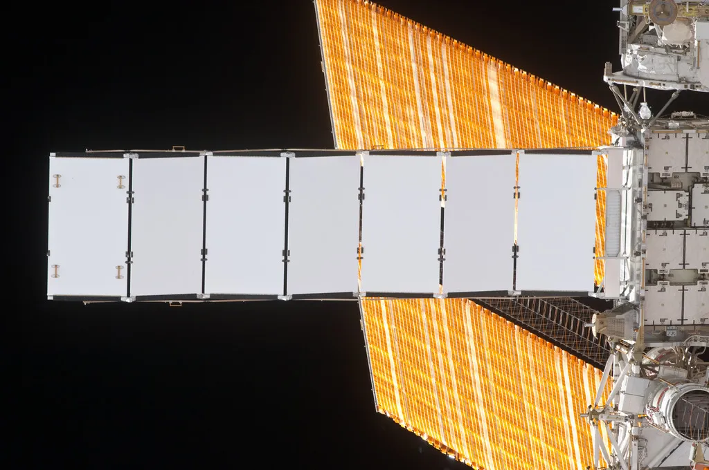
Top image: Nadir view of the S4 Truss radiator, taken by an STS-130 crewmember aboard the orbiter Endeavour during its approach for joint operations with Expedition 22. An S4 solar array wing (SAW) is also visible. Source: NASA