A new satellite image arrives, but roads sit slightly beside their mapped centerlines, building roofs extend beyond existing footprints, and a utility corridor appears to have shifted. Before moving any GIS features, check how both datasets were positioned. A sharper or newer image does not automatically provide a more accurate ground reference.
Misalignment can come from coordinate systems, datum transformations, image geolocation, terrain correction, viewing angles, or the GIS layer itself. Identifying the cause matters: the same offset that makes a map look untidy can also create false construction alerts or misleading boundary-crossing results.
Three Different Measures of Image Quality
Spatial resolution describes the level of ground detail an image can represent. Ground sampling distance, commonly quoted as pixel size, is related to this detail but does not guarantee that every object of that size can be identified. Resampling an image to smaller pixels does not create additional observed detail.
Absolute positional accuracy describes how closely image features match their actual ground coordinates in a specified reference system. A detailed image can still be displaced relative to a surveyed road intersection.
Image-to-image registration accuracy describes how closely corresponding features align between images, including acquisitions from different dates. It is especially important for change detection: the same unchanged road should occupy consistent positions before its surroundings are compared.
These measures answer different questions. Two images may align closely with each other while sharing an offset from surveyed coordinates. Conversely, images that are suitable for general mapping may still require additional co-registration before detecting small changes.
Which Dataset Should You Trust?
When a surveyed utility line does not match the latest imagery, moving the line until the overlay looks correct can introduce an error into the asset record. The image may be displaced, the GIS layer may have a coordinate problem, or the two datasets may represent different physical features.
For an underground pipeline, the photograph may not show the asset at all. A visible trench, access road, or vegetation strip is not sufficient evidence of its exact position. Editing the pipeline to follow those features requires supporting survey or engineering information.
Surveyed data also needs verification. Check its collection method, coordinate reference system, accuracy documentation, and whether it represents an as-built location or a planned alignment. Select the reference using traceable evidence and the task’s requirements.
A parcel boundary needs similar care. A visible fence, hedge, or roof edge does not necessarily represent the recorded boundary. An apparent crossing should trigger review of image geometry and boundary provenance before it is reported as an encroachment.
Recognize the Pattern Before Correcting It
The distribution of the offset provides useful clues. A consistent displacement across flat ground suggests different causes from an error that grows on hillsides or affects only tall buildings. The patterns below guide investigation; they do not establish a diagnosis on their own.
A Five-Step Check for Newly Delivered Imagery
1. Confirm the Metadata and Coordinate Systems
Start with the original geospatial delivery. Record the acquisition date, sensor, processing level, pixel size, coordinate reference system, and stated positional accuracy. Where available, review the viewing angle, elevation model, control information, and quality report. Record equivalent information for the GIS layer.
Check the datum as well as the projection, zone, and units. Where high precision requires it, also confirm the datum realization and coordinate epoch. A shared map display does not prove that the correct transformation has been applied.
Defining a coordinate system and reprojecting data are different operations. Defining assigns the correct interpretation to existing coordinates; reprojection calculates coordinates in another system. Relabeling data to match the map’s coordinate system can introduce an error rather than resolve one.
2. Choose a Reference with Documented Accuracy
Use a reference whose accuracy is sufficient for the intended decision. This could be surveyed visible points or independently validated reference imagery. A convenient web basemap is not automatically suitable for checking engineering-scale offsets.
Also establish whether the datasets are independent. Agreement between two layers derived from the same image does not provide independent evidence of absolute accuracy.
3. Compare Stable Ground Features
Select features that are clearly identifiable and unlikely to have changed: ground-level pavement corners, durable road markings, or surveyed targets visible in the image. Confirm that each comparison identifies the same physical point.
Avoid using moving shadows, seasonal vegetation, water edges, or roof corners as general ground references. A roof corner and a building’s ground corner can have different apparent positions in an off-nadir image.
Distribute observations across the area, including its edges, different elevations, and mosaic seams. Agreement at one intersection does not establish agreement throughout the delivery.
4. Measure Local Offsets and Verify Any Correction
For each comparison point, record the east–west and north–south displacement in a suitable measurement system. Inspect the direction and magnitude of the offsets, then map where larger discrepancies occur.
If the image is adjusted, reserve separate check points that are not used to calculate the correction. Control points help fit the model; independent check points test its result. Low residuals at the fitted control points alone do not establish delivery accuracy.
The report should state the reference, point count and distribution, measurement method, horizontal error statistics, and remaining problem areas. Report errors in ground units and, for image-to-image registration, pixels. Distinguish measured results from a supplier’s product specification.
5. Decide Whether the Data Fits the Task
Compare the remaining uncertainty with the smallest change or clearance that matters. Broad land-cover monitoring, individual-building change detection, and pipeline clearance assessment have different requirements.
If an apparent change is comparable in size to the local registration error, flag it for review. Do not apply one universal pixel threshold to every sensor, landscape, and detection method. Test the intended workflow on representative unchanged and changed areas before relying on its alerts.
Why Orthorectification Is More Than Moving an Image
Orthorectification corrects image geometry using sensor information, terrain information, and control or reference data. It accounts for distortions that vary across a scene, including those associated with perspective and relief.
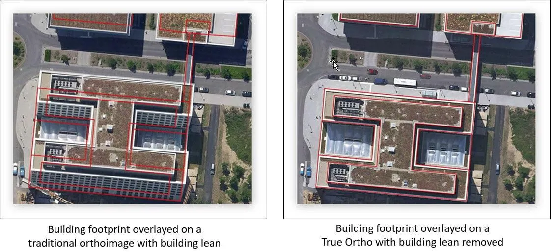
A uniform shift may address a verified translation bias. It cannot, by itself, correct varying terrain displacement or make every elevated roof coincide with its ground footprint. An orthorectified image can retain building lean when above-ground structures are not adequately represented in the correction.
Rotating, stretching, or straightening an image in a graphics editor may improve its appearance, but it does not establish mapping accuracy. A visually convincing result can still contain incorrect scale or local distortion.
Preserve the original delivery and document any geometric correction. Ask the supplier to clarify the product’s processing level and accuracy before treating an edited image as a measurement source.
A Real Example: False Building Changes in Changsha
A 2016 study by J. Chen, J. L. Hou, and M. Deng examined building-change false alarms using 0.5-meter WorldView-2 imagery of a residential area in Changsha, China. The images were acquired on December 13, 2011, and March 25, 2015.
The researchers addressed differences associated with viewing and illumination conditions. In their test, a building-change method produced 85 detected objects. Visual interpretation identified 35 of those objects as false alarms; the proposed additional analysis alleviated 26.
This was not a test of a simple scene-wide offset, and those results are specific to the study. It demonstrates a related operational problem: unchanged buildings can generate change alerts because their appearance and apparent geometry differ between acquisitions. Checking ground registration is essential, but it does not eliminate every source of urban false change.
For a customer reviewing a suspicious building alert, compare the ground-level surroundings, roof displacement, shadows, and acquisition geometry. Confirm physical change using additional imagery or other evidence before updating the asset record.
Ask for a Delivery You Can Evaluate
A useful imagery delivery should make its intended use and geometric limitations clear. Before ordering, specify whether the priority is general visualization, alignment with surveyed assets, or comparison with historical imagery. Request the relevant metadata and agree on how acceptance will be checked.
For monitoring, retain the reference dataset, processing version, independent check results, and locations requiring manual review. This makes it possible to distinguish a real site change from a change in the imagery or processing.
STARPATH GLOBAL helps customers select satellite imagery around the target size, monitoring task, and GIS integration requirements. Explore our imagery catalog for suitable resolution options, or discuss your existing GIS layers and accuracy requirements with our team before ordering. Customers building a new monitoring workflow can also apply to the Pioneer Partner Program for support from our Forward Deployed Engineers.