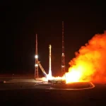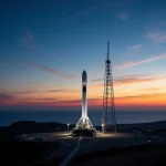
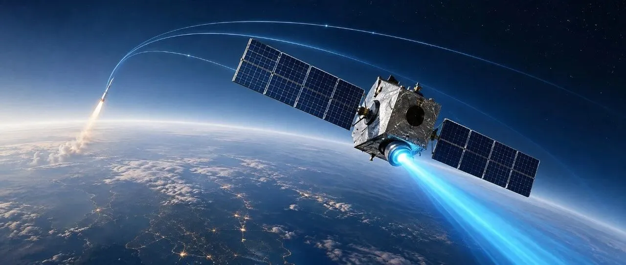
A successful rocket launch is followed by satellite separation. At this point, many people assume the mission is essentially complete: the rocket has delivered the satellite into space, and the satellite only needs to power on and begin operations.
However, for many low Earth orbit (LEO) constellation missions, the orbit delivered by the rocket is an “injection orbit” rather than the final operational orbit where the satellite will spend its service life. Due to constraints such as multi-satellite launches, fairing volume, launch windows, and rocket performance allocation, satellites may need to adjust their own orbital altitude, phase position, and operational configuration to reach mission requirements.
This is where the satellite’s electric propulsion system takes over. Unlike chemical rockets with their spectacular flames, electric propulsion produces thrust so small that it can be compared to the weight of only a few grams or several dozen grams. Yet it can operate repeatedly over weeks, months, or even longer periods, accumulating tiny velocity increments from each orbital maneuver until they become significant orbital changes.
Rockets rapidly deliver satellites into space, while electric propulsion gradually moves them to the positions where they need to operate. The former is like a sprint; the latter is like steadily accumulating progress over a long distance.
I. First, Be Precise: Electric Propulsion Does Not Send Satellites From the Ground Into Space
“Rockets send satellites into space, electric propulsion sends them into orbit” is an intuitive expression, but it is not a fixed process for every mission. Many satellites are launched directly into orbits close to their final operational altitude. In these cases, electric propulsion is mainly used for station-keeping, formation adjustment, or end-of-life disposal. Other missions adopt a “lower injection orbit + autonomous satellite orbit raising” approach, transferring part of the orbital maneuvering task from the rocket to the satellite.
The key distinction lies in thrust levels. Launch vehicles must provide enormous velocity increments within a short period to accelerate spacecraft to orbital velocity. Electric propulsion produces much lower thrust and is generally unsuitable for launching from the ground or replacing chemical propulsion in rapid avoidance maneuvers that must be completed within seconds.
Its strength lies elsewhere: after a spacecraft has already entered space, electric propulsion can use small amounts of propellant to gradually and precisely modify the orbit over long periods.
China National Space Administration (CNSA) defines electric propulsion as a propulsion system that uses external electrical energy to heat or ionize propellant and then ejects it at high velocity to generate thrust.[1]
Therefore, “getting into space” and “reaching the mission orbit” are not the same operation. The former is primarily a launch problem, while the latter involves orbital dynamics and mission design. The two processes can be completed entirely by the launch vehicle, or they can be divided between the rocket and the satellite propulsion system.

Figure 1: The handover between chemical rockets and electric propulsion during orbital insertion. Source: Author’s illustration.
II. Why Can Rockets Finish the Job in Minutes While Electric Propulsion Needs Months?
The Core Issue Is Not Which Technology Is More Advanced, but the Trade-Off Between Thrust and Specific Impulse
Rocket propulsion relies on reaction force. An engine ejects propellant backward at a certain velocity, giving the spacecraft forward momentum. Chemical rockets excel because they can consume large amounts of propellant within a short time and generate enormous thrust. The cost is rapid propellant consumption, as well as intense operating conditions for engines, tanks, pipelines, and thermal protection systems.
Electric propulsion also works by ejecting propellant, but instead of relying on chemical energy, it uses electrical power to accelerate propellant particles to much higher exhaust velocities. Engineers commonly use specific impulse (Isp) to describe propellant efficiency: with the same propellant mass, a higher exhaust velocity produces greater total impulse.
NASA’s small spacecraft technology reports describe electric propulsion as a combination of high specific impulse, low thrust, and long operating duration.[2]
The trade-off can be expressed through three basic relationships. In an idealized model:
T=ṁve
Isp=ve/g0
and the approximate power requirement of electric propulsion is:
P ≈ Tve/(2η)
where η represents system efficiency.
Increasing exhaust velocity reduces propellant flow requirements, but accelerating particles to higher speeds requires more electrical power.
This is why electric propulsion is not simply a case of “higher thrust is always better.” Satellites need sufficient solar array capability and electrical power capacity, while also managing the heat generated by the system. Thrust, specific impulse, power, efficiency, lifetime, and mass must all be balanced for a specific mission.
A Number Helps Show How “Slow” Electric Propulsion Really Is
Assume a 2,000-kilogram satellite equipped with an electric propulsion system producing 20 millinewtons of thrust. Ignoring attitude losses, gravity losses, and orbital perturbations, its acceleration is:
a = T/m = 0.02/2000 = 1×10^-5 m/s²
After continuous operation for one day, the theoretical velocity increment is approximately 0.864 m/s.
A velocity change of 0.864 m/s may seem insignificant, but if it is accumulated in the correct direction every day, it becomes tens of meters per second after several weeks and hundreds of meters per second after several months. Conversely, if a mission requires rapid orbital changes within seconds or minutes, this level of thrust is far from sufficient.
Electric propulsion does not rely on a single powerful burst. Its advantage comes from extending small thrust over a long operating period.
As a reference point, NASA’s Psyche asteroid mission uses four Hall thrusters, each capable of producing approximately 240 millinewtons of maximum thrust. NASA compares this thrust level to the weight of a single AA battery held in the hand. For a spacecraft weighing nearly one tonne, this remains “slow pushing,” but over long durations it can complete deep-space orbital transfers.[3]
III. What Exactly Makes Up a Satellite Electric Propulsion System?
Many popular explanations describe electric propulsion simply as “a Hall thruster.” From a spacecraft systems engineering perspective, this is far from sufficient.
A complete electric propulsion mission requires, at minimum, propellant storage and feed systems, thrusters, power processing, electron neutralizers, measurement sensors, thermal control structures, attitude and orbit control software, as well as ground testing and in-orbit operation procedures.
ECSS-E-ST-35-01C also treats electric propulsion engineering as a multi-dimensional discipline involving functions, interfaces, environments, design, quality, operations, and verification.[5]

Figure 2: The energy chain, propellant chain, and control chain of an electric propulsion system. Source: Author’s illustration.
1. Propellant Storage and Feed System: Electric Propulsion Still Needs “Fuel”
The “electric” in electric propulsion refers to the energy source, not the propellant.
Without propellant, there is no mass being expelled and therefore no reaction force to generate thrust. Common propellants include inert gases such as xenon and krypton. Some emerging systems are also exploring iodine, which can be stored at high density.
Gas propellant systems typically require tanks, pressure regulators, valves, filters, pressure and temperature sensors, and flow controllers.
Propellant selection is not simply a matter of choosing the cheapest option. It depends on storage density, supply pressure, discharge characteristics, material compatibility, lifetime requirements, and supply chain considerations.
Xenon offers excellent performance and mature technology but has limited availability and relatively high cost. Krypton provides advantages in some applications due to lower cost and availability. Iodine can be stored as a solid at room temperature, but requires heating for sublimation, creating additional engineering challenges involving material compatibility, contamination control, and stable flow regulation.
2. PCDU Manages the Spacecraft, PPU Powers the Propulsion System
PCDU stands for Power Conditioning and Distribution Unit. It belongs to the spacecraft platform power system.
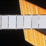
It receives electrical energy from solar arrays, batteries, or other power sources and performs functions including bus regulation, power distribution, load switching, current protection, fault isolation, and status monitoring. It then supplies power to subsystems such as attitude control, communications, payloads, thermal control, and propulsion.
NASA’s small spacecraft power system documentation places PCDU/PMAD systems at the center of managing spacecraft electrical power from generation sources to different loads.[10]
PPU stands for Power Processing Unit. It is a dedicated component of the electric propulsion subsystem.
The PPU receives power from the spacecraft power bus managed by the PCDU and converts it into the specific electrical outputs required by the thruster, including discharge power, magnetic coil power, anode power, cathode heater/keeper power, and flow controller power. It also participates in ignition, steady-state regulation, telemetry, fault protection, and shutdown operations.
NASA’s publicly available Hall electric propulsion PPU documentation states that the PPU provides regulated power to the thruster and propellant flow control components. ESA electric propulsion documentation also identifies the PPU as a key power component of electric propulsion systems.[11]
The basic power chain is:
Solar arrays/battery → PCDU → electric propulsion power interface or spacecraft bus → PPU → thruster, cathode, magnetic coils, and flow control system
Some small satellites integrate certain functions into a single power electronics unit, while others use near-bus-voltage direct-drive architectures. However, specific hardware interfaces determine the actual configuration, and product integration does not mean the two concepts should be considered identical.
3. Hall Thrusters: Not “Pushing With Magnets,” but Accelerating Plasma Through Electrons, Ions, and Electric Fields
A Hall thruster generally contains an annular discharge channel. A propellant such as xenon enters the channel as neutral atoms. A cathode supplies electrons to the discharge region, while an anode establishes the discharge potential.
Electrons have very low mass and are easily influenced by magnetic fields. Ions, with much greater mass, are more strongly accelerated by electric fields. This difference in behavior between electrons and ions is the foundation of Hall thruster operation.
In a simplified model, the magnetic field is primarily radial, while the electric field is mainly axial. Electrons undergo azimuthal drift under crossed electric and magnetic fields, creating what is known as the Hall current. Because of this motion, electrons remain longer inside the channel and collide with xenon atoms, converting some neutral atoms into positively charged xenon ions.
The term “Hall” does not refer to a separate Hall sensor, but rather to this electron transport behavior in crossed electromagnetic fields.
The ionization and acceleration processes are coupled within the discharge channel. The electric potential distribution, plasma density, and electron temperature vary depending on operating conditions, so the electric field is not simply a fixed “voltage plate.” However, from an engineering perspective, the process can be summarized as follows:
The magnetic field extends the electron path; electrons convert propellant into plasma; the electric field accelerates ions out of the thruster.
The ion beam carries positive charge. If only positive ions were expelled, the spacecraft would gradually accumulate electrical charge and the beam would suffer from space-charge effects. Therefore, Hall thrusters require a cathode or neutralizer to inject electrons into the plume, making the exhaust approximately electrically neutral.
The thrust comes from the momentum carried away by high-speed particles. Electrons mainly support plasma generation and charge neutralization rather than providing the primary thrust mass.[5]
The long-term challenges of Hall thrusters also come from this operating principle. High-energy particles can erode channel walls and magnetic structures. Cathodes must withstand heating, ignition cycles, and continuous electron emission. Magnetic shielding, channel materials, magnetic topology, and operating point control all affect lifetime, efficiency, and thrust stability.
For long-duration missions, engineers often use magnetic shielding and other design approaches to reduce ion bombardment of channel walls. However, lifetime must still be demonstrated through testing rather than inferred only from initial thrust measurements.[12]

Figure 3: A Hall thruster ionizes propellant and accelerates it into a high-speed ion exhaust stream. Source: Author’s illustration.
4. Gridded Ion Thrusters: Separating Ion Generation From Ion Acceleration
The gridded ion thruster discussed here is a typical electrostatic ion propulsion system.
The propellant first enters a discharge chamber, where an electron source ionizes neutral atoms and creates plasma containing positive ions and electrons. Unlike Hall thrusters, which couple ionization and acceleration within an annular channel, gridded ion thrusters extract ions from the discharge chamber and accelerate them through a set of perforated grids.
A simplified structure usually includes a screen grid, acceleration grid, and deceleration grid. The positively biased screen grid attracts ions toward the grid openings. The acceleration grid provides a strong negative potential difference, accelerating ions through the apertures and increasing their axial velocity. The deceleration grid helps control the exit potential and beam boundary, reducing excessive divergence.
The number of grids and voltage configurations vary among different designs, so these three layers should not be interpreted as identical for every product.
The grid apertures function similarly to a set of microscopic electrostatic lenses. Aperture size, grid spacing, open area ratio, voltage difference, and plasma meniscus shape together determine ion beam current, divergence angle, and thrust.
If grid spacing is too small, manufacturing and assembly difficulty increase. Excessive voltage differences increase insulation and breakdown risks. If the ion beam deviates from the intended operating condition, grid erosion and performance degradation may occur.
After passing through the grids, ions also require a neutralizer to supply electrons and keep the exhaust beam approximately electrically neutral.
Gridded ion thrusters can achieve extremely high exhaust velocities and specific impulse, but they are sensitive to grid geometry accuracy, plasma distribution, beam alignment, grid erosion, and neutralizer lifetime.
The real engineering challenge is not simply producing an ion beam, but maintaining acceptable beam quality, thrust, power consumption, and contamination levels throughout the required mission lifetime.
5. Thermal Control, Structures, and Plume Effects: Electric Propulsion Is Also a High-Energy Management Problem
During operation, only part of the input power is converted into exhaust kinetic energy. The remainder becomes heat.
This heat must be conducted through the spacecraft structure and ultimately radiated away. Thruster mounting location, thrust direction, and center-of-mass offset influence attitude control. Energetic particles and sputtered materials may also contaminate solar arrays, optical payloads, star trackers, or radio-frequency surfaces.
Therefore, an electric propulsion unit is never simply “installed and switched on.” It must undergo vacuum testing for thrust, plume behavior, erosion, ignition stability, power characteristics, electromagnetic interference/electromagnetic compatibility (EMI/EMC), and lifetime performance.
NASA’s electric propulsion laboratory capabilities include precision thrust measurement, thruster erosion diagnostics, plume characterization, and electromagnetic compatibility testing.[4]
IV. Where Does Electric Propulsion Actually Take Satellites? Four Typical Mission Roles

Figure 4: Four typical applications of electric propulsion in satellite missions. Source: Author’s illustration.
Type 1: Initial Orbit Raising and Orbit Circularization
After rocket separation, a satellite first completes deployment, attitude stabilization, and health checks. The spacecraft then plans electric propulsion firings based on the determined orbit.
The thruster does not simply point “upward” toward space. Instead, it usually operates along the orbital tangential direction or another suitable direction in the orbital coordinate system. A single burn changes velocity; the velocity change modifies orbital energy; after the satellite reaches another point in its orbit, additional firings continue the process under new orbital conditions.
A Hall electric propulsion mission publicly reported by China Aerospace Science and Technology Corporation (CASC) provides a clear engineering example. A 300-watt Hall electric propulsion system operated for more than 110 days, completed over 600 ignition cycles, accumulated more than 400 hours of operation, and raised a low Earth orbit satellite’s altitude by nearly 300 kilometers.
This case demonstrates that electric propulsion orbit raising is not a single large maneuver, but the accumulation of many small adjustments over a long period.[6]
Type 2: Orbit Maintenance
Low Earth orbit satellites experience atmospheric drag from the extremely thin upper atmosphere, causing orbital altitude to gradually decrease. The Earth’s non-spherical gravity field, solar and lunar gravitational effects, and solar radiation pressure also modify orbital parameters.
Electric propulsion can provide periodic compensation with small thrust, extending operational lifetime.
For geostationary satellites, electric propulsion can also perform north-south station keeping, east-west station keeping, and other long-term orbital control tasks. ESA summarizes typical Hall thruster applications as orbit maintenance, lifetime extension, and formation flying.[7]
Type 3: Constellation Phasing and Configuration Adjustment
A satellite constellation does not automatically form its final arrangement after launch.
Individual satellites must reach their designated orbital positions by adjusting orbital phase, orbital period, and in-plane relationships. The high specific impulse and repeatable operation of electric propulsion make it suitable for these precise, long-duration maneuvers.
Electric propulsion does not necessarily allow satellites to “move quickly,” but it enables them to gradually achieve and maintain the carefully designed distribution required by a constellation.
Type 4: End-of-Life Deorbiting
After a satellite reaches the end of its operational life, it still occupies orbital space.
For low Earth orbit satellites, electric propulsion can lower orbital altitude and allow atmospheric drag to accelerate reentry. The required deorbit speed and duration depend on orbital altitude, satellite mass, and mission requirements.
Deorbiting is not simply a matter of pressing a button. Engineers must consider remaining propellant, attitude stability, communication windows, collision risks, and the intended reentry region.
V. How Does a Satellite Know Where It Is and Where to Push?
Electric propulsion is not as simple as switching on a thruster and “spraying upward.”
Orbital maneuvering begins with determining the satellite’s current state: position, velocity, altitude, eccentricity, inclination, and uncertainty range.
Low Earth orbit satellites may combine navigation receivers, ground-based orbit determination, onboard attitude sensors, and flight-control software to estimate their orbit. Deep-space missions rely more heavily on ground-based range and Doppler measurements, attitude measurements, and dynamic models.
The mission planning system then converts the target orbit into firing windows, thrust directions, power modes, and attitude commands.
The spacecraft control system must also continuously monitor:
- propellant pressure;
- propellant flow rate;
- thruster current and voltage;
- cathode condition;
- temperatures;
- solar array power;
- attitude errors.
Any abnormal condition may trigger power reduction, premature shutdown, or switching to backup modes.
Electric propulsion places particularly strict requirements on attitude control. If the thrust direction deviates from the intended orientation, part of the maneuver designed to increase orbital energy may instead alter orbital inclination or introduce unwanted disturbances.
At the same time, solar arrays must be positioned to provide sufficient power, while their orientation may affect thruster plume direction and thermal conditions.
Propulsion, attitude control, power, thermal management, and telemetry systems therefore become a tightly coupled spacecraft-level engineering problem.
VI. Why Does Electric Propulsion Save Propellant, Yet Remain Technically Challenging?
The First Cost Behind High Specific Impulse: Power
High specific impulse does not come for free.
Accelerating propellant to higher velocities requires more electrical energy. High-power electric propulsion systems often require larger solar arrays, stronger power management systems, and improved thermal rejection capability.
During eclipse periods, batteries must support both spacecraft loads and propulsion power transitions.
Solar array size, pointing constraints, and degradation over time must all be considered during mission design.
The Second Cost: Lifetime and Erosion
Inside a thruster, high-energy ions, electrons, plasma, and high-temperature components interact continuously.
Channel walls, magnetic shielding structures, grids, and cathodes may experience erosion, contamination, or performance drift.
Small variations in propellant flow can change discharge conditions and thrust performance. Frequent ignition cycles can also increase stress on cathodes and power electronics.
The Third Cost: Time and Mission Scheduling
Electric propulsion orbit raising may require months.
During this period, satellites must continue performing communications, attitude control, thermal management, and telemetry functions.
Ground teams must continuously schedule firing windows, determine orbit changes, evaluate spacecraft status, and respond to anomalies.
If constellation deployment schedules require rapid operational rollout, electric propulsion systems must balance thrust, power demand, and automation capability.
The Fourth Cost: Electric Propulsion Cannot Replace Every Propulsion Method
When missions require rapid orbital changes, emergency collision avoidance, or large instantaneous impulses, chemical propulsion, cold gas propulsion, or other high-thrust systems remain valuable.
Hybrid configurations are also common: chemical propulsion handles rapid maneuvers, while electric propulsion performs long-duration high-efficiency operations; or electric propulsion completes the primary mission while smaller thrusters are retained for attitude control and emergency operations.
The optimal architecture depends on mission requirements. There is no single propulsion solution suitable for every spacecraft.
VII. From a Single Thruster to an Industrial Supply Chain: Where Are the Real Challenges?
For an electric propulsion system to enter operational service, it must pass multiple engineering gates:
Can the thruster ignite reliably and operate stably?
Can the PPU provide long-term power output?
Can propellant flow be accurately controlled?
Can tanks and valves maintain reliability?
Can thermal and plume effects remain acceptable?
Can software automatically handle abnormal conditions?
Can the spacecraft withstand electrical, structural, and interface impacts?
Finally, can the entire system prove its performance through vacuum, thermal environment, and lifetime testing?
This is why electric propulsion is not simply the business of a single “engine manufacturer.”
Propellant storage and supply involve pressure vessels, valves, filtration, heaters, and material compatibility.
PPU development requires high-voltage power electronics, semiconductor devices, control software, and EMI/EMC design.
Thruster development requires expertise in plasma physics, magnetic circuits, cathodes, erosion-resistant materials, and precision manufacturing.
The spacecraft itself must integrate solar arrays, batteries, thermal radiators, attitude control systems, and telemetry systems into a unified architecture.
Public information from China Aerospace Science and Technology Corporation indicates that the 502nd Institute of the China Academy of Space Technology has developed a Hall electric propulsion product series covering 100-watt, 300-watt, 600-watt, and 1100-watt classes for different spacecraft masses and orbital missions. According to publicly released figures, these products had been applied on more than 100 satellites by the reported date.
These figures represent the product and application statistics released by the organization and should not be interpreted as the total size of the entire electric propulsion market. However, they demonstrate that electric propulsion is moving from technology demonstration toward standardized and large-scale deployment.[8]
NASA’s 2026 State-of-the-Art of Small Spacecraft Technology report also identifies in-space propulsion, power systems, and orbital transportation as continuously evolving technology areas. It emphasizes that technology maturity depends on mission payloads, reliability requirements, and operating environments.
In other words, the fact that a technology can ignite successfully in a laboratory does not mean that a complete propulsion system can operate reliably on a spacecraft for ten years. Between the two lies a complete chain of verification and qualification.[2]
VIII. Three Common Misunderstandings About Electric Propulsion
Misunderstanding 1: Electric Propulsion Does Not Need Fuel
This is inaccurate.
Electric propulsion still requires propellant. Electrical energy is only the source of energy used to accelerate the propellant.
Without xenon, krypton, iodine, or another working fluid, the thruster has no mass to eject backward and therefore cannot generate reaction force.
Misunderstanding 2: The Higher the Specific Impulse, the Faster the Satellite Travels
This is also inaccurate.
Specific impulse mainly describes propellant efficiency. It does not directly represent instantaneous acceleration.
The typical characteristics of electric propulsion are high specific impulse, low thrust, and long operating duration.
To determine how long a satellite takes to reach a target orbit, engineers must consider many factors, including spacecraft mass, thrust level, available power, operating duty cycle, orbital design, and attitude constraints.
Misunderstanding 3: Electric Propulsion Will Replace Rockets
This is inaccurate.
Electric propulsion is an in-space propulsion method for satellites. It is not a replacement for launch vehicles that lift spacecraft from Earth.
A more accurate description is:
Rockets deliver spacecraft into space and initial orbits, while electric propulsion takes over when additional orbital maneuvers are required.
They are not competing technologies in the same race. They are two stages of the same relay.
Conclusion: The Satellite’s “Second Journey” Begins After Separation
When a rocket ignites, everyone can see the enormous thrust.
When electric propulsion operates, there may be only a faint plasma plume and a slowly changing orbital trajectory.
Yet for a satellite, separation does not mean arrival. It marks the transition from the launch phase into the operational phase.
The spacecraft must know where it is, determine where it needs to go, and calculate how every firing changes its orbit.
At the same time, solar arrays must provide power, the PPU must deliver stable electrical output, propellant must flow reliably, thrusters must operate in vacuum for long durations, and thermal and attitude control systems must handle all the effects introduced by the propulsion system.
Rockets carry satellites away from Earth. Electric propulsion transforms every tiny exhaust pulse into long-term freedom of movement in space.
As satellite missions become increasingly complex, selecting the right spacecraft platform, payload configuration, and in-orbit capabilities has become a key factor in mission success. With China’s rapidly expanding space manufacturing capacity, global customers can access increasingly competitive satellite platforms, payload solutions, and customized space systems. STARPATH GLOBAL helps organizations design and source satellite solutions tailored to specific mission requirements, from customized spacecraft configurations to application-oriented space services. Explore our custom satellite solutions or contact our team to discuss how space technology can support your next mission.
References
[1] China National Space Administration (CNSA): “How Electric Rockets Travel Through Space: Nuclear Electric Rockets as a Future Trend,” February 24, 2016. Introduces electric propulsion systems that use electrical energy to heat or ionize propellant and generate thrust.
[2] NASA Small Spacecraft Systems Virtual Institute: 2026 State-of-the-Art of Small Spacecraft Technology, In-Space Propulsion chapter and report overview, May 2026.
[3] NASA Science: Psyche Spacecraft. Public information on solar electric propulsion, Hall thrusters, xenon propellant, and individual thruster performance.
[4] NASA Glenn Research Center: Electric Propulsion and Power Laboratory. Public information on electric propulsion vacuum testing, power systems, thrust measurement, erosion diagnostics, plume characterization, and EMI/EMC testing capabilities.
[5] European Cooperation for Space Standardization: ECSS-E-ST-35-01C, Liquid and Electric Propulsion for Spacecraft. Defines engineering requirements for spacecraft electric propulsion systems covering functions, interfaces, environments, design, quality, operations, and verification.
[6] China Aerospace Science and Technology Corporation (CASC), China Space News: “Hall Propulsion System of the 502nd Institute Successfully Completes Low Earth Orbit Satellite Raising Mission,” September 21, 2022. Reports a 300-watt system operating for more than 110 days, completing more than 600 ignition cycles, accumulating over 400 hours of operation, and raising orbit altitude by nearly 300 kilometers.
[7] European Space Agency (ESA): “Compact Electric Thruster Cleared for Space Firing,” June 27, 2023. Introduces the HT100 low-power Hall thruster, xenon propellant, propellant management components, PPU, and planned in-orbit orbit-raising and lowering demonstrations.
[8] China Academy of Space Technology (CAST), China Aerospace Science and Technology Corporation: “Hall Electric Propulsion System Applications Exceed 100 Satellites,” December 10, 2025. Introduces the 100–1100 watt Hall electric propulsion product range and reported in-orbit applications.
[9] NASA/JPL: Fundamentals of Electric Propulsion: Ion and Hall Thrusters, Chapter 1 Introduction. Used for verifying fundamental relationships among specific impulse, exhaust velocity, power, and thrust.
[10] NASA Small Spacecraft Systems Virtual Institute: 3.0 Power. Describes PCDU/PMAD functions in spacecraft electrical energy regulation, distribution, load switching, protection, and fault isolation.
[11] NASA Glenn Research Center: Power Processing Unit (PPU) for Small Spacecraft Electric Propulsion. Describes how PPUs provide regulated power to Hall thrusters and propellant flow control components, including discharge power, magnetic coil power, cathode functions, and flow control.
[12] NASA Glenn Research Center / NASA Technical Reports Server: Advanced Electric Propulsion Flight System. Describes long-life Hall thruster systems, including PPU discharge power, magnetic coils, cathodes, flow control, telemetry, and fault protection functions.